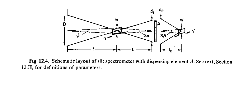
A spectrograph is an instrument which separates different wavelengths of light so they can be measured independently. Most spectrographs work by using a dispersive element, which directs light of different wavelengths in different directions.

The dispersion depends on the characteristic of the dispersing element.
Various elements can be characterized by the angular dispersion,
![]() , or alternatively, the reciprocal angular dispersion,
, or alternatively, the reciprocal angular dispersion,
![]() . In practice, we are often interested in the linear
disperion,
. In practice, we are often interested in the linear
disperion,
![]() or the reciprocal linear dispersion,
or the reciprocal linear dispersion,
![]() where the latter is often referred to simply as the dispersion in
astronomical contexts, and is usually specified in Å/mm or Å/pixel.
where the latter is often referred to simply as the dispersion in
astronomical contexts, and is usually specified in Å/mm or Å/pixel.
If the source being viewed is extended, it is clear that any light which comes from regions parallel to the dispersion direction will overlap in wavelength with other light, leading to a very confused image to interpret. For this reason, spectrographs are usually used with slits or apertures in the focal plane to restrict the incoming light. Note that one dimension of spatial information can be retained, leading to so-called long-slit spectroscopy. Also, if there is a single dominant point source in the image plane, or if they are spaced far enough (usually in combination with a low dispersion) that spectra will not overlap, spectroscopy can be done in slitless mode. However, note that in slitless mode, one can be significantly impacted by sky emission.
The resolution depends on the width of the slit or on the size of the image in slitless mode, because all a spectrograph does is create an image of the focal plane after dispersing the light. The ``width'' of a spectral line will be given by the width of the slit or the image, whichever is smaller. In reality, the spectral line width is a convolution of the slit/image profile with diffraction and the disperser response function. Note that throughput may also depend on the slit width, depending on the seeing.
Given a linear slit or image width, ![]() (or an angular width,
(or an angular width,
![]() , where
, where ![]() is the focal length of the telescope) and
height
is the focal length of the telescope) and
height ![]() (or
(or
![]() ), we get an image of the slit
which has width,
), we get an image of the slit
which has width, ![]() , and height,
, and height, ![]() , given by
, given by


Using this, we can derive the difference in wavelength between two
monochromatic sources which are separable by the system.

The resolution is usually characterized in dimensionless form by

Note that there is a maximum resolution allowed by diffraction. This
resolution is given aproximately by noting that minimum angles which
can be separated is given by approximately ![]() , where
, where ![]() is the width of the beam at the camera lens, from which the minimum
distance which can be separated is:
is the width of the beam at the camera lens, from which the minimum
distance which can be separated is:


Image slicers: preserving resolution and flux.
Fiber spectrographs: multiobject data.
Slitlets: multiobject data.